


New energy-saving antifreeze technology for air-cooled units
Release Time:
06 Aug,2022
Project Background 
In water-scarce northern regions, air-cooled units have developed rapidly. However, winter antifreeze for the air-cooling system is a crucial issue during winter operation.
Due to early steam condensation, low-temperature zones easily appear at the bottom of the parallel flow tube bundle and the top of the counter-flow tube bundle. The condensation water flow at the lower end of the parallel flow tube bundle increases, leading to freezing. Although the amount of steam and condensation water decreases at the top of the counter-flow tube bundle as the condensation process completes, the water vapor in the non-condensable gas may still form flocculent ice, blocking the flow area of the finned tubes. The parts of the air-cooling system prone to icing are the lower part of the parallel flow heat exchanger tube bundle and the upper part of the counter-flow heat exchanger tube bundle.
The main causes of air cooler icing are: The steam flow entering the air-cooling system is too small, and the heat dissipation load is too low. Even if all fans are stopped and natural ventilation is used, local low temperatures cannot be avoided. Under natural ventilation, uneven air flow in the air-cooled island is easily caused, so local overcooling will cause local icing of the tube bundle. Counter-flow units are usually more prone to icing than parallel flow units, and units at the edge of the air-cooled island are more prone to icing than those inside.
There are also some other problems during the operation of the air-cooling system, such as high backpressure in summer, lack of basis for backpressure setting, and uneven steam distribution in the air-cooling radiator during unit start-up, shutdown, and night or low-load operation when the turbine exhaust steam volume is small. To ensure antifreeze and safe operation of the air-cooling radiator, the unit backpressure is usually controlled above 15 kPa, preventing the air-cooled island from operating in the most economical backpressure range.
Since the ambient temperature in high-cold regions is usually below zero in winter, the exhaust temperature of thermal power units is much higher than the ambient temperature due to design limitations. Generally, the operating backpressure is not lower than the blocking backpressure. Especially during deep peak regulation, the exhaust volume is small, and the subcooling of the condensate is large, making the air-cooling system more prone to freezing. Common adjustment methods include reducing the fan speed until it stops, reversing some fans for warming, etc., with no other means in extreme situations. Common antifreeze measures include windbreak, insulation, and removing some air-cooling rows.
New energy-saving technologies for antifreeze in air-cooled islands 
From the heat transfer equation, Traditional air-cooling antifreeze technology reduces the heat transfer coefficient, insulation, and heat transfer area. Among them, the reduction of the heat transfer area is limited by the amplitude of load changes, while insulation and reducing the heat transfer coefficient have already reached their current limits. Therefore, we propose to use the method of reducing the logarithmic mean temperature difference of heat transfer to further prevent freezing. Specifically, it means reducing the backpressure, reducing the subcooling of the condensate, and reducing the difference between the exhaust temperature and the ambient temperature.
From a safety perspective, Deep peak regulation of the unit requires ensuring that the pressure difference of each stage of the turbine is within a reasonable range, and the steam flow of each stage of the turbine meets the continuity equation, that is, the steam volume is within the allowable range. The blocking condition is that the exhaust volume is greater than the maximum allowable value, and the general exhaust blowing is that the exhaust volume is less than the minimum allowable value.
For extraction and heating units, when the heat load increases and exceeds the supply, the low-pressure cylinder blowing and the intermediate-pressure cylinder exhaust blowing should be considered; when the heat load decreases or the unit actively increases the heat supply, the low-pressure cylinder blowing and the intermediate-pressure cylinder exhaust overpressure should be considered.
For pure condensing units, the turbine may blow at low loads and the backpressure may block at high loads. The current ultra-low backpressure flexibility transformation of heating units is a successful application case.
Through technological transformation, improve the low-backpressure vacuum capacity of the unit's vacuum system. Under the normal operation mode of the original vacuum equipment, at low ambient temperatures, the unit's operating backpressure can be reduced as the load decreases.
At an ambient temperature below zero, when the unit is at 50% load, the unit's operating backpressure can be reduced from the original 10 kPa to 5 kPa, and when the deep peak regulation is at 30% load, the unit's operating backpressure can be reduced to 3.5 kPa. The low-load backpressure reduction process during winter unit peak regulation is stable, and the subcooling of the condensate does not increase. The temperature field of the air-cooled radiator is uniform, and there is no phenomenon of locally low temperature.
Combining the actual operation of the turbine, starting from the optimization and transformation of the vacuum equipment and the reduction of the process resistance of the vacuum pipeline in the air-cooled island, the unit can achieve ultra-low backpressure operation at low temperature and low load.
1. Vacuum System Antifreeze and Energy Saving Analysis
Under the new power supply and demand situation, higher requirements are put forward for the deep peak regulation capacity and safe and economical operation of the unit. The role of solving the high pressure of air-cooling system antifreeze and achieving ultra-low backpressure operation, improving the unit's peak regulation capacity and the economic efficiency of low-load operation will be more obvious.
At present, the minimum operating backpressure of most direct air-cooled units in winter is around 8-10 kPa. In severely cold areas, the actual operating backpressure is even higher. Under the existing vacuum conditions, limited by the minimum antifreeze flow, the unit still maintains a higher backpressure operation at low loads, and often uses passive antifreeze measures such as fan shutdown, derating, and blocking to solve the antifreeze problem of the air-cooling system. The energy-saving potential of achieving low backpressure operation at low temperatures and low loads has not been exploited.
Theoretical basis for ultra-low backpressure antifreeze operation of direct air-cooled units in winter: By improving the suction capacity of the vacuum system, reducing the unit's limit backpressure, and reducing the content of non-condensable gas in the vacuum system, and at the same time, by transforming the vacuum pipeline system and optimizing the balance of the air extraction resistance of each unit in the air-cooled system, the situation of severely uneven subcooling distribution is reduced. On this basis, the steam flow in the air-cooled island is smoother, solving the problem of overcooling and blocking of the counter-flow unit. At the same time, due to the decrease in operating backpressure, the heat transfer temperature difference between the exhaust steam in the air-cooled island and the outside air is reduced, weakening the heat transfer, thereby achieving ultra-low backpressure operation of direct air-cooled units in winter, solving the antifreeze pressure and improving the unit's economy.
After the modification, the backpressure of the air-cooled unit during winter operation can approach the blocking backpressure corresponding to the exhaust steam volume of the corresponding low-pressure cylinder. At ambient temperatures below zero degrees Celsius, the unit's operating backpressure can be reduced from 10 kPa to 5 kPa at 50% load, and the power generation coal consumption can also be reduced by no less than 7 g/kWh; at 30% load, the unit's operating backpressure can be reduced from 10 kPa to 3.5 kPa, and the unit's power generation coal consumption can be reduced by more than 15 g/kWh.
2. Optimization and Modification of Turbine Vacuum Equipment
The existing vacuum system of the unit has a limit backpressure of 3 kPa, which cannot meet the requirements of ultra-low backpressure operation. An auxiliary vacuum device needs to be connected in series to increase the inlet pressure of the existing vacuum equipment by more than 2.5 kPa. The limit backpressure of the auxiliary vacuum equipment should reach below 1 kPa, and its own vacuum volume flow rate should reach 4-5 times that of the existing single vacuum equipment. The auxiliary vacuum system should be equipped with a large-capacity cooling device to ensure that the water vapor extracted by the auxiliary vacuum equipment is fully condensed. The partial pressure of the inlet steam of the original vacuum equipment should be controlled within the range of 2.5 kPa. If necessary, the temperature of the original closed cooling water should be cooled.
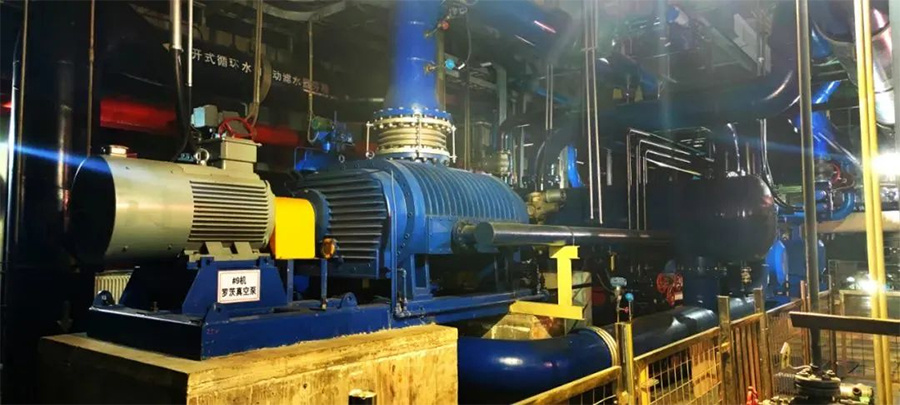
Application Diagram of Roots Vacuum Pump
The technical route for vacuum equipment can choose between two schemes: high-performance Roots vacuum pumps or steam ejectors. The Roots vacuum pump should be an air-cooled pump and capable of variable frequency regulation. The auxiliary vacuum system is tentatively considered to be located at the zero-meter level of the turbine room, near the original water ring vacuum pump, connected to the front of the original water ring vacuum pump main pipe through a series connection, and adding large and small bypasses for easy start-up, shutdown, and removal.
3. Optimization and Modification of Air-Cooled Island Vacuum Pipeline to Reduce Flow Resistance
Considering the layout and resistance characteristics of the air-cooled condenser vacuum pipeline in the power plant's air-cooled system, after the modification of the auxiliary vacuum equipment, the capacity of the overall vacuum system increases. If the size of the original vacuum pipeline remains unchanged, the pressure drop along the pipeline will increase simultaneously, resulting in an increase in the overall resistance of the vacuum system. Therefore, the vacuum branch pipeline needs to be modified (the overall flow capacity is considered to be no less than 2.5 times), so that the resistance of the air extraction branch pipeline system is reduced.
After the expansion modification of the vacuum branch pipeline, the original manual vacuum isolation valve needs to be modified simultaneously. At the same time, the original air-cooled island platform horizontal vacuum connecting main pipe is gradually reduced in diameter. This section of the pipeline needs to be modified and replaced with a through-diameter pipeline, or a through-diameter pipeline needs to be added to the air-cooled platform (the original vacuum main pipe is connected to the newly added pipeline, and the expanded branch pipeline is connected to the newly added pipeline) to reduce the resistance of the vacuum system.
Add Temperature Measurement Equipment to the Air-Cooled Island

 1. Antifreeze Warning
Using the air-cooled system temperature field monitoring device, through Monitoring the temperature field Help Judge the unevenness of air-side flow resulting in local overcooling. It helps to judge the uneven distribution of steam-side flow under low flow conditions, causing local overcooling. When the ambient air temperature is below 0°C, by monitoring the outlet air temperature of the finned tube bundle, the heat dissipation state of the tube bundle can be indirectly judged, which can help to judge the possibility of ice formation in the tube bundle. Combining data such as backpressure, condensate temperature, and subcooling, regulations are made for the low temperature of the hot air at the outlet of the radiator tube bundle, and it is correlated with the condensate temperature, which can achieve antifreeze warning for the air-cooled system and take corresponding antifreeze measures before the air-cooled tube bundle freezes.
2. Monitoring Hot Air Recirculation
The flow field of the air-cooled island is easily disrupted by natural wind. The air heated by the air-cooled system is re-sucked into the air-cooled system inlet by the air-cooled fan, resulting in hot air recirculation. By monitoring the inlet air temperature of the air-cooled radiator, it can help judge the degree of hot air recirculation and calculate the hot air recirculation rate By monitoring the air-cooled temperature field to judge the occurrence of hot air recirculation, the operators can respond promptly and perform predictive adjustments to reduce shutdowns, boiler shutdowns, or load shedding.
3. Monitoring Ash Accumulation and Pollution of Air-Cooled Finned Tubes
Air-cooled radiators are prone to ash accumulation affecting heat exchange Through temperature field monitoring, a reasonable high-pressure flushing scheme is formulated, the cleanliness of the radiator locally and overall is evaluated, and cleaning operations are guided.
4. Optimizing Air-Cooled Operation
Like wet condensers, air condensers also have indicators such as end difference and temperature rise to evaluate the operation of air condensers. Using the air-cooled temperature field monitoring device can make up for this deficiency. The air-cooled system is large, and the air flow field and steam-side flow distribution are easily uneven. By monitoring the air-cooled system temperature field it provides a basis for the operation personnel's adjustments, and under the premise of unit operation, reduce backpressure, increase vacuum, achieve energy saving and emission reduction, and optimize air-cooled operation for the purpose.
5. Application of Temperature Measurement Cables on the Air-Cooled Island
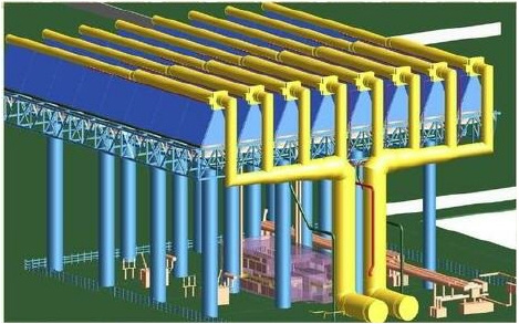
Air-Cooled Island Schematic
A temperature measurement cable is arranged every one meter in the vertical height direction on both sides of the Type A cooling tower, and a temperature measurement point is arranged every 960 mm in the horizontal direction.
A temperature collector is installed on each set of heat sinks. The data bus cable connects all the collectors, and through the RS485 interface, it is connected to the network communication box, converted into a fiber optic signal, and transmitted over long distances to the control room via fiber optics. The data processing server processes and displays the data.
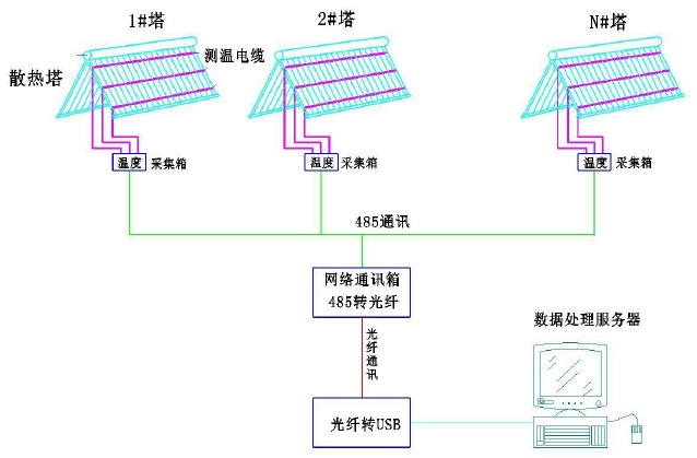
Air-Cooled Island Temperature Measurement System Diagram
The temperature sensing cable uses a steel wire protective tube, and the outside is installed with a digital temperature sensor in a high-pressure, high-temperature, corrosion-resistant, waterproof, and flame-retardant industrial-grade rubber sheath. The temperature measurement range is -55℃~+125.0℃, with an accuracy of ±0.5 ℃. High strength, wear-resistant and tensile.
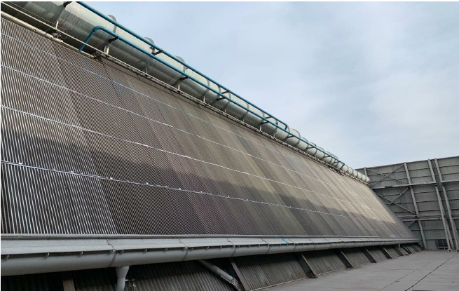
Air-cooled island cooling tower temperature sensing cable layout diagram
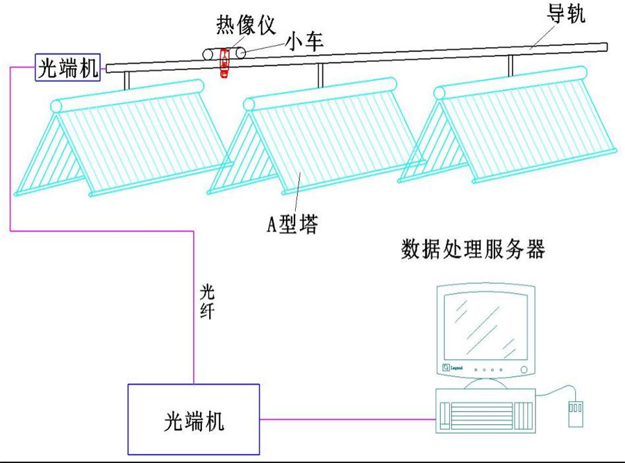
6. Application of track platform thermal imaging temperature measurement in air-cooled island
Install a fixed bracket on the upper end of the air-cooled island radiator, and install a guide rail on the fixed bracket. Install a movable smart cart on the guide rail, and install an online thermal imager with an automatic focusing lens on the cart. Realize the acquisition of temperature information of the direct-cooling unit radiator.
Each time the cart moves to the middle of two groups of A-type towers, control the thermal imager to rotate one circle to collect the temperature of the air-cooled island radiator. The temperature information collected by the thermal imager is transmitted to the remote data server via fiber optics. The real-time collected thermal images are processed, recorded, and alarmed through thermal infrared analysis software.
Conclusion
Combined with the actual operation of the steam turbine, from the optimization and transformation of vacuum equipment and the vacuum pipeline of the air-cooled island Reduce process resistance Starting from optimization and transformation, the unit can achieve ultra-low backpressure operation under low temperature and low load, and at the same time increase the temperature measuring equipment of the air-cooled island Improve the real-time detection methods for operation personnel Therefore, the problem of air-cooled island antifreeze is solved, and the backpressure is reduced, improving the efficiency of the unit, achieving two goals with one action.
Direct Air Cooling
Indirect Air Cooling
Next Page:
Related News
Start up and draw the bow fully!
27 Feb,2026
How can we assist you?
If you are interested in our products, please leave your contact information
Service Hotline:
E-mail:
Address:
Block A, Guoan Building, Second Lane, Dongcheng Road, Xiaodian District, Taiyuan City, Shanxi Province
Shanxi Dewang Energy Saving Technology Co., Ltd. Powered by 300.cn | Privacy Policy